Imagine what losers work at NSA: "The NSA and other elite intelligence agencies devote millions of dollars to hunt for common software flaws that are critical to stealing data from secure computers." Need more be said?
http://www.wnd.com/2014/04/nsa-exploited-heartbleed-bug-for-intelligence-for-years/?cat_orig=us
What sort of government refuses to make a simple law that disallows anyone from entering someone else's computer without permission? A computer is a private possession, yet the government wants us to grow up in the Internet age accepting the fact of life that large organizations can crash your computer at any time that you go online. But then, for the government itself to pay people to find ways to sneak into your computer, it's a cesspool of society's greatest losers, worse by far than people who prefer to live on the streets. It's no wonder you're brown, Obama, you've been swimming in the cesspool.
I apologize that two webpages in the last update were not available for most of the week. The two holes in the towers, that is.
In this update, the unbelievable happens. I find two more images of the north hole and conclude right off that the fantastic engine claim in the last two updates could not be correct no matter how I calculate the wing line in question, but by the time the update is only a day old, the evidence of drastic photo tampering is beyond doubt. Midway through the update, things become confusing as to how the images in the last update differ from the new ones found here. By the second-last day, I feel some sense has been made of the differences, and yet questions remain.
I have a picture from Simon Shack (below) with a plane superimposed on the north-tower hole. I'll call it the low-resolution image for this discussion. Mr. Shack either placed this plane on the hole himself, or borrowed it that way; it could be the official-storyline plane position. Simon is one who looks photographs over very carefully; his "claim to fame" (for lack of a better phrase) is scrutinizing photographs for the purpose of proving that no planes hit the towers. Yet, this image is of such low resolution that it would surprise me greatly if it came from the Shack library of images. I imagine he has possession of every north-tower hole available from online, and so if he used this low-resolution one to make his points, it may underscore how few crisp images are available of the hole.
http://imagizer.imageshack.us/a/img689/5540/wtc1hole1qb.jpg
If the image disappears, see it here:
http://www.tribwatch.com/photos/911ShackNHole.jpg
One thing that the low-resolution image reveals, though not really, is that the workers who created the hole did not do a very good job. The plane is positioned as best as possible to meet the hole's requirements for both wing tips, but even then the positioning of the plane is such that it's going to strike many columns. By the end of the update, it's realized that this hole is wrong, not the original, and has been reduced in horizontal distance by two, while not reducing the vertical distances, and then doubled in size again. Until realizing this, I had been confused.
I'd like to add that, as I'm writing now, I have no idea what Shack has said about this image. I imagine that he'll discuss the problems between the plane's shape and the hole "design." But what I'd like to do is first give you my impressions before reading his. This is not a discussion for you if you're into thrilling fictionals. If you carry a calculator and pencils in the top pocket of your white shirt, you've come to the right place. I'll put the math in these { } brackets so that, if you choose to skip it, you can go to the bottom line. I'll also make the bottom line start with THEREFORE in caps.
First, I need to measure the plane that's in the image to see if it checks out. {When the tip-to-tip distance of the plane is 10.75 inches on my screen, the horizontal tip-to-tip distance is 9.7 inches. As the latter figure spans 41.5 columns (a meter apart), its distance is 136 feet, meaning that each inch of the 9.7-span equals 14.0 feet.} THEREFORE, the plane superimposed on the image works out to (10.75 x 14 =) 151 feet, less than two columns short of a 767's wing span of 156 feet. The wing tip should therefore go very near the very last part of the far-left damage, and the center of the plane could come slightly to the left. It's on the hole perfectly, for all intents and purposes here, and yet it's obvious that the picture is not to be trusted as the reality.
The left wing is too high for my claim of the last update. It places the left engine within the hole, but I claimed that the engine and its housing should have struck down at the floor. And so my work is cut out for me in this update to show why the plane, as positioned in the low-resolution image, must be wrong. You decide whether I'm arguing truthfully, or merely to prop up my own pet theory. I'm challenging myself to be honest about this, whatever the outcome. By the time the update is finished, I have NOT proven the engine claim of the last update.
Unfortunately, I don't have a draw package to provide images with my own lines, planes, or whatever else might be useful for you to follow along. Therefore, I'm going to name some of the columns, even though I know how bad you are for remembering names. In the image below, where we see a woman leaning against a column, that's going to be called the jagged column. You're going to hear about this column much, so get familiar with its position. The three columns with ends at the same level, above her head, will be called the triplet. The two tall white ones to the far-right of the picture will be called the two center columns. The two severely bent columns to her right will be called the bent columns. Thank you for complementing me on my creativeness.
http://www.tribwatch.com/photos/911NorthHoleWoman.jpg
Let me say: if that is a real woman in the image, my heart goes out to her for what she suffered. Fortunately, she may not be real. She's there for a reason, and it's probably not to wave at the helicopter. A person waving to a helicopter in that situation does so with both hands with an air of panic, not like she's passing a pleasure craft on the seas where the people there are waving to her, and she's just waving back casually. She would look more real by being in the wide open, not beside a column that makes her less visible.
I can tell you right now that my claim is impossible judging by the height of the woman, for she makes the center columns far taller than a person, and thus places the center of the plane way up above the floor level (that she stands on) so that engine damage is expected above that floor. Until having this image, obtained after the last update was written, I could not tell how high the center columns were with the two images worked with at that time. With this low-view image, it appeared that the left wing came nearly horizontally along the floor...so that the engine should strike the floor. As you can see, the entire floor remains undamaged.
The good news, the holes in the two images above are not at all the same. The trick is to discover which of the images was the original. The official storyline does NOT use the low-view image. By the end of the update, it is realized that this image is a serious threat to the perpetrators. The image has come to me at a very good time; it's an image that they want no one in the world to possess.
Put all images in this discussion on a separate browser because I'm sending you often to all of them. Or, better yet, you can save the images to your computer and open them there.
There are many problems to point out in the image with the woman. The first thing I'd like to point out is the pair of bent columns as seen in the low-view image. One can make out both bent columns, but the one is very visible, while the other's bend is not visible. Look at how the bent one begins bending at the floor, and rising little off the floor. As the white concrete cladding is only about 18 inches wide (I'm guessing), it appears that the bent piece of column reaches little more than 20 inches off the floor. Plus, look at how sharp the angle of that bend is, more than 45 degrees.
Take your thick glasses out from your white shirt pocket. Let's go to the image with the woman for to look at the same bent column. It looks phony, more like the handle of a frying pan than a square column. That's our first clue. Enlarge the photo greatly while keeping some decent resolution. The angle of the column doesn't look at all the same, does it? Just switch from one image to the other if you want a good laugh. The tip of this column is way up off the floor, about eight feet by the looks of it, forcing us to locate the wing line way up there.
If the wing passed some eight feet off the floor, how do we explain that the column upon which the woman is leaning, and the one beside that, are sliced along the floor line? Such a mystery, but the low-resolution image allows an answer. The two columns, which I'll call the pair of sliced columns, are between the bent column under discussion, and the jagged column that she leans on. How possibly could some of the concrete cladding (it's what makes for the jagged look) remain on the jagged column, while the two neighboring columns are sliced at the floor? It demands that the wing came in above this jagged cladding, while the engine came in and sliced the neighboring columns at the floor, skimming the floor but not crashing directly into it. That's what they had intended for us to believe.
Now look straight up at the triplet hanging down from two floors above. None of the three columns are bent whatsoever. The two sliced columns were once attached to the triplet. How did the wing possibly disconnect the columns from the triplet without bending it? The columns do not merely butt together end-to-end (with a weld seam), but rather they telescope together for a certain distance prior to being locked / welded in place. It doesn't matter if they telescope as little as four inches, there is no way to pop a pair of columns from their joints without first bending the columns back...or ripping the socket open. But if a welder's torch came by and cut the columns, no problem. It could be done quietly, out of view. Which do you think is the more-likely scenario, cutting the columns with airplane wings, of a welder's torch?
In the low-view image, we can see the bottom ends of the triplet (they look perfectly square). It's suggesting that this is where one joint was, which checks out. As we see none of the ends of the triplet having a cracked socket, we must assume that these are the smaller ends that slip/telescope into the sockets. The image below shows columns in the installed position, but I cannot make out whether sockets are up.
http://911research.wtc7.net/wtc/evidence/photos/wtc12consenr.html
[After this update was out, the page below was found showing an actual joint. See near the floor in the real photo. I'm not sure how to interpret what may or may not be inside the columns where the ends meet.
http://www.911hoax.com/morgan_reynolds_911_hoax.html]
If the engine struck way down, just above the floor, why should these particular columns get their sockets ripped out some 12 feet up from the floor? Some will say, but wait, the plane in the low-resolution image has the wings striking at the top of these columns, right where the sockets are...in which case, we then ask why the same columns should be sliced way down at the floor. Something seems wrong, and it is: the low-resolution image is a fake. It's wrong by the wing line alone, which is exactly why it's a low-resolution image: to hide this problem.
The idea seems to be that the torch cutters were instructed to cut two columns at the floor level because this would feign passage of the engine. In the low-view image, look into the background of the hole beyond these two columns to see that, indeed, it looks like a round object entered in. In the low-resolution image, where the engine is directly above the two sliced columns, the jagged column is touching the engine, but, when the wing line is brought lower, the engine housing should fit smack in the jag.
In other words, we are finding here that the plane is NOT positioned correctly on the crash hole, as per how the idiot club had planned the wing lines. It's an important point. It's additional evidence for my claim that the shape of the crash hole, in the low-resolution image, has been altered from the real shape seen in the low-view image.
The jagged section (just the white part above the woman's head) has a roundish shape, as does the engine housing. It appears that the "audience" of this "show" was to get the impression that the jagged section was cut out by contact with the engine housing. It looks like they did their homework better than I thought. The engine's heavy-metal part (i.e. minus the softer housing) is only about four feet in diameter at most, so far as I was able to make out in the last update, and so it's wide enough to contact two neighboring columns. If you imagine the engine skimming the floor line, the housing will fit perfectly (or so it seems) into the jagged part of the concrete slab. I think we have their game figured out. Yet, they ended up positioning the engine well above the jagged section. Why? I was able to figure this out by the end of the update.
The same drastic V-shape seen in the low-resolution image applies to the wing line in the south-tower hole. Did the plotters plan on feigning a different type of aircraft in the beginning, only to change it to a 767 later? If that's not true, how do we explain this v-shape? On the other hand, the wing line in the low-view image does not suggest a v-shape.
There is another question formed by the image below showing yet another view of the north-tower hole. As much as I dislike all those redundant red arrows, I'll call this the red-arrow image:
http://www.tribwatch.com/photos/911HoleNorth2.jpg
The Concrete-Floor Problem
Three triplets to the left of "the triplet" under discussion above, there is one column severely mangled. It's banged in below the floor, and cut above the floor at its joint. Yes, this is at the joint too, perfectly in line with the joints of "the triplet". The part that's come away is the socket end, and yet we cannot see whether the socket was actually ripped apart (it wasn't because no plane struck) due to the cladding remaining in the way of our sight. How convenient to leave the cladding on, therefore, where one expects the cladding to be knocked off here more than anywhere else.
To accomplish the banged-in look with a team of workers, the mangled column would be pulled with a chain / cord from below the floor. Two columns to its immediate right have slight bends at the top of the floor flange. VERY BAD, for the concrete is midway between flanges, as you will see below. Have you understood the problem -- that exposes this fakery -- with bending the columns at the tops of the flanges?
There are steel joists under the concrete that butt up against the floor flange, thus helping to maintain the integrity of the flange below the concrete. BUT THERE IS NOTHING above the concrete, har har, to maintain the flange's integrity, snort snort, so that there can be no reason -- in a plane strike -- for the bending of the columns at the tops of the flanges. There was nothing but air and wallboard on the other side of those flanges above the concrete. All bends in the columns are expected midway between flanges, where concrete offers the hard resistance. Now you understand why this image is a fake.
If one removed some joist sections under the floor, as well as some concrete, one could also bend the flange inward, as we see it. Just use a chain and pulley under the floor to bend the columns, though that method would first necessitate cutting each column on at least three sides (not visible to the camera), and softening the metal with red-hot heat on the fourth side to be bent.
IMPORTANT: bends located at the tops of the flanges (rather than at floor level) can be explained in that workers could not get access to the columns (for cutting and bending) at floor level, for the flange itself was in their way. It's not as though they didn't know that the concrete was about 1.5 feet below the tops of the flange, for they were standing on the concrete when performing this trick. The rabbit is out of the hat. They wanted for us to believe that the concrete was at the top of the flange. WRONGO!
Besides, they stabbed themselves in the foot by creating the impression of wings slicing through columns without cracking the concrete behind the bends. That is, they left the impression that the wing strike was unable to budge the concrete floor, but instead forced columns to bend. That's the message that their "artwork" necessitates. It's very bad for the idiot factory because it begs the question of how the wings got through the concrete. This concrete problem was briefly discussed in the last update; in short, if the wings can penetrate the concrete like a hot knife through butter (as their picture requires), the wings should also push the columns into the concrete like a hot knife through butter...yet in the hole we see the very opposite.
Whether the columns are bent or otherwise, no column to the left of the triplet has been pushed through the concrete floors. One might say, but wait: the entire span of the wing to the left of the triplet is between floors, and so none of the wing there needed to penetrate any concrete. And I would say that the workers arranged for this situation as best they could, but were incapable of doing the same on the right side of the plane (not to mention in the south tower)...where they left the impression of the wing penetrating the floors.
In studying the left-side wing line in the low-resolution image, you can see it passing across the part of the floor flange that's cut on a diagonal (see the red-arrow image for the diagonal). This cut -- concrete and steel together -- was supposedly produced by the wing. As you can see, the diagonal cut is just before the wing arrives to the engine. This produces a contradiction with a picture of the engine skimming the floor. Ultimately, this will reveal to me that the diagonal cut was a creation of a photo doctor. The diagonal cut was NOT there originally. In fact, evidence will arise later that this floor, with the diagonal cut, is improperly positioned, for which reason and more I've wondered whether it was a total fabrication (i.e. there was no such floor at this level).
Finding the True Wing Line?
A careful study of the dings and slices in all left-side columns, in the red-arrow image, demands that the wing line skim along the top of the white jagged column, about five feet below the wing line in the low-resolution image (and some three feet above the head of the woman). The engine housing, if eight feet in diameter, then skims the 94th floor (on which the woman stands)...but as the housing isn't strong enough to slice columns, this wing line is not good enough. It's not yet as low as the idiot club had planned it. The heavy-metal engine is yet some two or three feet off the floor if we use this wing line.
The reason that this wing line is wrong becomes visible when we accept the low-resolution image as a fake, for the two images with the woman have hole shapes that are replicas of the hole shape in the low-resolution image. The latter image has columns twice as high as the low-view image, meaning that the jagged column in the images with the woman shows twice as tall as the reality.
The great problem for the low-resolution image is that, when lowering the left wing even by five feet at the left-side engine, the right-side wing line shoots right off the map, so to speak. That wing line no longer conforms to the slices in the columns.
We are to believe that the wings were like Packman, eating up all the columns as he passes by. If the wing passed through, there shalt not be any column remaining in its path. Unfortunately for the lawless criminals, that's the law that they must abide by. Something went wrong with their original image, and they needed to doctor it while keeping wing lines along the slices. They don't have the luxury of locating the wing line wherever they choose.
We are not yet near the end of the problems. We are only starting to become familiar. In the red-arrow image, count four columns to the left of the triplet. The gap between column ends in this location is less than a wing-spar width, if we measure using the measuring sticks inherent in the images themselves. The floor flange immediately above the gap has not been bent by the passage of the wing, oddly enough. To the right of this gap, the gaps increase in size in an unexpected way. There are now two wing lines possible, one along the upper parts of the gaps that go on an upward slope, and one along the bottom sides of the gap that go more horizontally. Can you see what they did? They doctored the image to provide the higher wing line as seen in the low-resolution image. It was NOT that way originally.
The next gaps to the left of the first one mentioned above are even less wide. At most, they are as wide as the cladding. This doesn't allow the passage of a wing with spar 24 inches wide or better. The first three gaps to the immediate right of the mangled column dictate the particular angle of the wing line. And that's why the red-arrow image is seemingly trying to hide the size / positioning of two of the three gaps. The bent columns reach much higher than the low-view image allows, in order to reinforce the false idea that the wing line sloped up along the diagonal cut in the floor flange rather than lower down.
We are only about midway across the wing at the three gaps under discussion. It seems that the outer half of the wing did not pass through the columns at all. How did the plane get into the building, therefore? What did the sociopaths have in mind for us to believe by this picture? Why would the idiot team leave no gaps for the last third of the wing spar? "Everybody saw" the plane fly right in. It couldn't have been an illusion if EVERYBODY SAW it.
Let's enlarge the red-arrow image much, and inquire concerning the couple of dings in two or more columns to the far left. How could the wings make just one ding per column? Did the crew get lazy? Was the hour late? Did the boss quit? A spar packs two flanges that are capable of creating two dings per column some 24 inches apart. But I see only one ding per column, and two to three feet of cladding gone above the dings. You have the choice of locating the spar either to the top or bottom of the dings; I choose to go with: to the top of the dings...because that allows for a wing line right through the middle of all three gaps. Suddenly, the wing line is fairly horizontal across the floor.
If you choose to go with the spar striking below the dings, you need to answer why the cladding yet remains there. You should not under-estimate this argument, for a wing spar positioned above the dings forbids a wing line under the diagonal cut in the floor flange. A wing spar above the dings and out the three gaps is a nearly horizontal line, and yet we also need to realize that the dings were added as part of the doctoring. We also need to answer why the gaps are not at first large enough to accept a wing spar. Without the two dings suggesting an upward slope, the wing line goes much-more horizontal across the floor.
You can call these the dings of death, and play along with those who insist that an airplane made this mess. Question: what happened to the right-side wing after it made the dings and cracked the cladding? In the video, we didn't see the plane so much as jolt before finding its way inside the building. Shouldn't it have jolted (i.e. sudden slowing of velocity) if a wing could no longer break a column? I count seven columns not broken through, for a distance of 23 feet. What does a plane partially in a building look like that has the last 23 feet of it's wings not penetrating the columns? From the factory, the wings angle back away from the building at all times as the plane slips in unhindered, but when no more columns are broken through, the wings must BEND BACK as the plane manages to slip all the way in. And that's why these are the pings of death, for they just rang the death knell on the sociopaths who doctored the red-arrow image.
The image at the link directly above shows the wings NOT bending back as the plane enters the south tower.
How can we understand their problem: making the dings and simultaneously leaving out the gaps? If the wings cease to make gaps, the wing tips cannot strike the building to make the dings. Were they drunk? Was this part of the sociopathic syndrome that ailed them? Or were the dings added later to help change the wing line? I see no other purpose. The dings do give the impression of a wing line rising up, because one ding, right next to another, is higher than the other.
One must assume that the original plan was to have a wing line more horizontal across the floor. Something changed that plan, and that something forced them to change the shape of the crash hole.
The Measuring Ruler Speaks
Look again at the low-view image (below) that I was working with when I made the trump-card claim. I emailed some 30 web-owners with this claim, only to find the two images with the woman the next day, which both made me feel very silly. Before that, I was 101 percent sure that the claim was correct. I've already started to tell you the reason for being so sure, due to the bent column looking like it's no more than hip high off the floor. The other bent column to its left likewise shows low off the floor. The jagged column looks lower than the two central columns, though it's higher than the central columns in the image with the woman).
http://www.tribwatch.com/911HoleNorth.jpg
The distance off the floor of the bent column, in the low-view image, can be measured by two methods: 1) using the distance between floors as a measuring stick; 2) using the width of the cladding or column spans as the measuring stick. The two measuring sticks do not nearly agree. Why not? Because the floor flange, with the diagonal cut, was pasted in. If we use that floor as part of the measuring stick, the bent column is about as high as half a storey. But, more absurd, the bent column reaches to within a few inches of this floor flange in the red-arrow image.
Although the low-view image is taken from below the floor line, it's not so far down that the measured vertical distances should be far off from the reality. Measure the two white central columns, for example, how they look no more than the height of a man's head. The pair are not much longer than the distance between two columns (two meters). Therefore, if the floor flange under discussion (the 95th floor) were not there, the next floor flange up would be the 95th floor, in which case the central columns would be about as tall as a man.
There's a solid grey line across the page that appears to be the concrete floor, yet the flange below that floor is not visible...unless it's the grey line itself. We are not supposed to see the concrete behind flanges. The floor flange with diagonal cut measures 5.3 feet off the floor when the column spans are used as the measuring stick. Unless midgets worked on this floor, this flange shouldn't be there. The idiot team does have an explanation for this, obviously, because it created the flange in the low-view image. The idiot team wishes for us to believe that the vertical heights are half the reality due to the picture being taken from low down. That idea cannot stand, which is why they don't want anyone to see the image, let alone assess its merits.
A measurement from the top of the floor, that the woman stands on, to the top of the flange up by the triplet (supposedly two storeys) is less than four column spans i.e. less than 13 feet. How about that. It measures exactly what we would expect of ONE storey. It's another reason to deny the existence of the flange with the diagonal cut.
It turns out that the concrete floor is NOT where it appears to be in the low-view image. It must be some sort of an intended Illusion that the grey line looks like a slab of concrete of 6-8 inches in depth. Looking at the construction image below (of the columns going up during construction of the towers), one can see that the concrete floor is MIDWAY between floor flanges. Much of the flange is still visible above the floor after it's been poured. This image may not have been online when the perpetrators created their holes, or, if it was, they may not have known about it. This image is very damaging to the perpetrators of the 911 mass murder if one knows how to use it in a court of law.
http://www.tribwatch.com/photos/911Columns.jpg
Simon Shack argues that the helicopters supposedly taking pictures that day could not have been. I have a digital camera purchased for $300 in about 2005 that has excellent resolution when the pictures are increased in size on a computer. Why do we not have such resolution available for these holes? First off, they don't want us to see inside the holes, which explains why they made them on the north and south sides of the towers, where the sun wasn't shining in the early morning. They had to bring the south tower down before the sun rose up to 11 am, at which time it would be shining very well inside the south tower hole. The north tower could wait longer.
I have great news to help prove fraud. In the last update, I failed to measure the height of the storeys in the construction image. Just now, it was found that the storeys are about 12 feet apart, roughly the same distance between what looks like the grey concrete slab (in the low-view image) and the flange way up at the triplet. Yet, the two images with the woman claim that there are two storeys between those two points.
{When the width of the flanges at the construction image measure four centimeters exactly on my screen, the distance from the concrete floor to the center of the flange above it is 11 centimeters exactly. It doesn't matter where the flange is measured, to the near right or left of the two foreground men: it's always 4 centimeters wide...showing that there is no distortion due to small distance away from the camera. It doesn't matter where the measurement of the columns is taken, whether to the right or left of the men, they are always exactly three centimeters apart center to center. A string of four columns is exactly 12 centimeters.} THEREFORE, as the latter distance is known to be four meters = 13.1 feet, it means that each centimeter on the screen corresponds to 1.09 feet so that the height from the top of the concrete to the middle of the next-storey flange (11 centimeters) is 12.0 feet! This measurement is probably not correct to the inch due to the fact that perfect measurements are unlikely by this method. But it's close.
Let's now do the math for the same height figured on the low-view image. The measurement's from the jagged column (where the woman will be standing). When the distance between the concrete floor and the middle of the next flange up is exactly seven centimeters on my screen, that distance measures horizontally 4 columns across (13.1 feet), center to center, minus half of one cladding width, for a total of 12.35 feet! Yet, this measurement is supposed to be over two floors...impossible.
I'm now going to down-size the low-view image until the vertical 12.35-foot distance is exactly three centimeters. {A horizontal distance of 12 centimeters, with the midway point directly under the jagged column, spans 16 columns = 52.5 feet minus half a cladding (.75 feet) for a total of 51.75 feet. As three centimeters is one quarter of 12 centimeters, we now find what one quarter of 51.75 is: 12.9 feet. THEREFORE, as we were expecting 12.35 feet as the answer, the 12.9 measurement (just 6.5 inches off) is close enough to verify that the screen method of measuring is acceptable.
The next problem is where the woman is standing in the image below. Her feet are level with the top of the flange, which is the top of what looks like the concrete floor in the low-view. HOWEVER, the construction image shows that the concrete floor should be midway between flanges. Why are her feet way above the concrete floor, therefore? I understand that she could be standing on deep debris, but as we can't see the debris she's on, it's also possible that she was pasted in by someone who wanted us to think that the concrete floors are at the tops of flanges.
http://www.tribwatch.com/photos/911NorthHoleWoman.jpg
Was she pasted in to give the impression of two storeys where there was only one? BEFORE YOU DENY this wild storey story, look at some of the evidence. The following was a welcome shocker. To verify whether the low-view image has an extra floor pasted in to force a conclusion of twice the vertical height than the measurements provide, one measures the height of the storey where the woman stands, but the measurement must be taken when the image is small enough that the top of the building shows. It may not be coincidental that they left the top of the building showing, for it helps to "prove" a (false) thing that they would like for us to believe.
After measured the height of the floor, the measurement was taken to the top of the building. When the distance between floors is about .6 centimeter, the distance to the roof is 9.7 centimeters. Dividing the numbers suggests 16 floors. As the red-arrow image tells that the woman was on the 94th floor, while Wikipedia claims 110 floors total, this measurement is perfect. It makes the perpetrators look correct with the existence of the floor with diagonal floor flange, but that's the reason that I suspected their showing the top of the roof at all, to create this false impression. I'm not disputing that there were 16 floors above the 94th, but am suspecting that they shortened the building to eight floors while cutting floor heights in half to make the eight appear as 16 floors.
I kid you not, that this suspicion was entertained against the odds. People would look at me funny even for thinking it. The idea that the perpetrators would actually cut the size of the building above the hole, in half, is ludicrous, right? But the evidence (shown above) suggested that this had to be the case. All I had to do was find a true image of the tower that showed twice as much height above the crash hole. Imagine the implications if this turned out to be correct. The next day, I came across the image below (camera angle about level with the hole) showing more than twice as much building, between the bottom of the crash hole and the roof, than in the low-view image! It's true. It was a profound moment. I've just emailed a no-planers bunch of online writers to inform them.
http://www.tribwatch.com/photos/911TowerNorth9am.jpg
When the tip-to-tip distance of the hole is about 3.6 centimeters, the distance from the floor upon which the woman stood to the top of the building is 4.3 centimeters, meaning that the distance is 1.2 hole lengths. But in the low-view image, the tip-to-tip distance is 16 centimeters when the height to the top of the building is .9.7 centimeters, or just .6 hole length. What's going on? That's exactly half the building, above the crash site, for the low-view image. IMPOSSIBLE. Take the people responsible for this image to court. Win a landslide victory.
Below is the tower from a camera shot on the ground. Does it look like the tower is twice as short due to the low angle? Of course not. Here's an image with the Empire State Building from a low view; does the top of the building seem crunched to half its true height. Of course not. Bring the people responsible for the low-view image to court. If you have the money, be a hero.
http://www.tribwatch.com/photos/911TowersGroundView.jpg
Where the distance from the bottom of the hole to the top of the building is 1.2 hole lengths, that's roughly 156 x 1.2 = 187 feet. If each of the floors were 12 feet tall, it works out to 15.6 floors. That works close enough.
When we measure, in the low-view image, 26 centimeters up versus 1.5 flange span, it works out to be about 17 floors, but when we use the 156-foot wing span as the measuring stick, the vertical distance (18 centimeters wing line versus 12 centimeters up) is just 8.5 floors, exactly half as much. Let's call this the vertical surprise. The surprise is, HALF as much.
BY WHAT COINCIDENCE is the camera, in the low-view image, supposedly positioned where the vertical distances are exactly HALF as much, thus playing wonderfully into a scenario with twice as many floors as is the reality? If you're smart, you'll realize that it has not to do with camera angle, but with the need of the damned of God to make one storey into one.
The image below shows the crash hole along with the entire width of the building. It indicates that the distance from both sides of the building to the wing-tip damage is about the same. The low-resolution image agrees, showing eight column between the damage and the edge of the building on both sides. This means that the far-right of the building, in the low-view image, is just one column outside of the top-right of the picture. So, when the vertical-surprise span is 9.7 centimeters on my screen, the width of the building is about 19 centimeters, a remarkable difference as compared to the 4.4 versus 4.3 respectively in the explosion image. In order for the numbers in the low-view image to be comparable, they would need to be 19 versus 19 rather than 9.3 versus 19. One sees that the comparison corresponds to HALF as much.
http://www.tribwatch.com/photos/911TowerNorth9am.jpg
This half-the-reality measurement is either due to the sharp camera angle (IMPOSSIBLE in this case), or due to doubling the number of floors. I say there is a trick afoot. If the camera truly were at a sharp angle, we would be able to see much more of the underside of the triplet columns, as well as the undersides of the cladding. Instead, that situation is roughly the same in both the low-view and woman images, even though the latter has a camera view that is quite horizontal.
Look again at the explosion image (as I'll call it) at the link above, and then knock off half the building above the hole. Imagine that half the building is not there, because that will give the picture that's in the low-view image. Does that seem right to you?
At first, I figured that, if one wants to see what the low-view image looks like when the vertical distance is twice as much (while keeping the horizontal as is), just look at both images with the woman. That's when I started to measure to find that the vertical distances in the one image with the woman had vertical increases chaotically. There is simply no explanation for the chaos aside from photo tampering.
To make these measurements, first bring the horizontal scales on the low-view and woman images to equality. The measurements below are taken when both images have a horizontal distance of about four centimeters from the outsides of both outer columns (23.2 inches per centimeter) in the triplet above her head. The comparisons between the two images are surprising and perplexing:
Image with Woman versus Low-View Image (in centimeters)
Dirty cladding: 5.5 v 3.0 (45% decrease)
Bare metal in the triplets: 1.8 v 1.1 (39% decrease)
Flange along triplet: 2.1 v 1.0 (52%)
Center floor flange: 2.0 v 1.7 (15%)
Lower floor flange at it's widest: 2.1 v .75 (64%)
Left-side central column from the top of grey flange: 3.7 v 3.0 (19%)
Bare metal top column, two to the left of triplet: 4.7 v 2.8 (40%)
Bent column from top of flange: 3.2 v 1.0 (69%)
That is completely astonishing. How do we explain the vast percentage differences? If one reduces the entire image with the woman uniformly, in vertical height, every vertical measurement would reduce by the same percentage. Not only do the figures show tampering inescapably, but the tampering requires explanations (I'm not going to attempt explanation in this update).
What I used to think was a poor attempt at feigning the grey concrete floor (low-view) upon which the woman stands is now realized as the entire flange that, for whatever reason, was left or made very small in comparison to the other flanges. It's obvious fakery, for one thing. And that's already good enough for me.
But let's go on to see what other incriminating things the idiots were forced to do. Look under the lowest floor flange, at the far left of the red-arrow image, to spot a diagonal piece of structural column. It's at a drastically different angle in the low-view image. The same change-of-angle applies to the large flange-like object beside the triplet. I'm not a camera expert, but I know enough that the only way for the angles of these two objects to change this drastically is for someone to reduce / increase the horizontal distance of the picture. It has NOT to do with the camera angle.
The Real Crash-Hole Shape
When comparing the hole in the low-view image with the sharp-v holes (eg. the low-resolution image), two things stand out. In the low-view hole, the height of the far-left black rectangle is shorter than the height of the larger rectangle to it's right by about the same amount as the same measurements in the sharp-v images. For example, when the far-left rectangle is the same height in both images, the other rectangle shows about the same height in both images. Below is a crisp image of a sharp-v hole:
http://www.tribwatch.com/photos/911HoleCrisp.jpg"
The main difference between the two rectangles is that, in the low-view, they are longer and therefore appear more narrow. The far-left rectangle is 4.4 centimeters long while the two sharp-v images shows only 2.3 centimeters long...though they are both one centimeter tall. Why is the low-view hole measuring TWICE as wide in this area, and why is its tip-to-tip distance so long that it should reach high above the roof?
Let's move on to the third rectangle from the left of the picture, while not changing the screen sizes as per the measurements above. For this measurement, we take the far-right column of the triplet in the crisp image above. The measurement from the very top of that column (at the very top of the hole) to the end of its white cladding is 4.5 centimeters while the distance from the same end of the cladding to the bottom of the hole (94th floor flange) is 3 centimeters. By comparison, the low-view image shows the same measurements. That wasn't expected.
Then, the eye-opener: everything to the RIGHT of the triplet column measures twice as far (or nearly so) in the low-view image. Everything to the LEFT of the triplet measures twice as far too (in the horizontal direction). How possibly could every vertical thing in the picture measure twice as far horizontally??? Simultaneously, the vertical distances are half as much as they are in the sharp-v images. That's HALF the vertical and TWICE the horizontal, wherefore it CANNOT be argued that this situation is due to camera angle.
I have never monkeyed around with a draw package to know whether there would be a difference in the resulting shape when expanding a certain object by two times in the vertical direction versus reducing its horizontal distance by two. The object, no matter how complicated its shape, may look the same shape either way; perhaps only the size changes.
If the horizontal was cut in half, while all vertical distances remained the same, the entire image needed doubling in size all around in order to fit properly on the width of the building. The final effect would be to keep the width of columns and cladding identical, but twice as long.
Or, the same result to columns and cladding would be effected if the vertical had been increased by two times.
One can readily understand that, with the right half of the picture twice as long, the wing line will not rise as abruptly. Was it their motive to change the right-side wing line? NO. For the alteration only made the wing line worse for their case. They altered the hole shape IN SPITE of creating a sharper v-shape for the wing line. Their motive for doing so must have been VERY important. Something must have gone seriously wrong with the explosion so that the original view had to be altered.
Both images show a roof line at about the same angle (though the camera view is coming from opposite directions between pictures), meaning that the variant measurements above cannot be due to varied camera angles. I realize that, with greater distance from the camera, measurements of the same items will appear to decrease in size, but, certainly, the hole in the crisp image cannot decrease half in size over less than 100 feet of horizontal distance from the camera. Besides, the hole in the low-resolution image matches with the hole in the crisp image, and yet the Shack camera view comes from the other direction (when the "horizontal" cladding lines go up on the page from left to right, as they do slightly in the low-resolution image, the camera is to the right of hole, and vice versa).
Obviously, the wing lines for a 767 would fit much better into the low-view picture, for which reason I'm taking the position that this hole shape (ignoring what we see inside of it) was the original = what the criminal team had planned, more or less. The only reasons I can see for having less building in the low-view image is: 1) to make it appear that the erroneous dimensions of the low-view image are due to a low-down camera angle; 2) it was the original position and shape of the hole in reality.
If 2) is the correct view, then they had to move the plane some eight or nine storeys lower, explaining they had to paste in floors.
Do you think that, from where this image looks to be shot from, the reduction in distance between floors of 12 feet or more would turn out to measure six feet at most? It's true that the distance between floors would appear to decrease with an eye view further down, but the angle of the photo seems to be greater than at 45 degrees (from the building). If we put a flat edge/object (such as a pocket calculator) facing our eyes flat at 90 degrees, it is not much shorter when turned to a 45 degree-angle.
Or, if you first look at a zero on your calculator as the calculator is held vertical directly in front of your eyes, and then, for comparison, hold the calculator vertical above your head at a 45-degree angle from your eyes, neither the calculator nor the zero reduces in tallness by half, not even close. Just view the zero, or even the window inside of which the zero sits, as the gap between floors to see what I'm getting at. In order to cut the window or zero to half its tallness, the calculator needs to be held way above the head on a very sharp angle of about 15 degrees. Try it.
Perhaps I'm treading where I shouldn't because I'm not a photography expert, but I'm doing my best, and, yes, I make mistakes, lots of them, when investigating difficulties. Plus, I'm writing as I investigate rather than after the investigation; expect some mistakes to be corrected for later, and feel free to use my work as a guide for your own.
Going again to the low-resolution image, let's get the size to the point where there are 1.75 centimeters between the lower cladding edge on the far-right triplet column and top of the floor where the woman stands below it. Now increase the low-resolution image until twice that span exists between the same two points. The horizontal distances are now about the same in both images, just how we want it. And the tip-to-tip distances, 24.5 centimeters, are also the same. The center of the plane's lowest point is 3.5 centimeters from the floor so that the plotters plotted on having it about 1.75 centimeters above the floor (i.e. everything in the low-resolution reduces to half the vertical height to get back to the low-view, original image), and that happens to be at the tops of the two, white central columns. (However, these columns must be reduced in height by half of what they now show.)
The right-side engine is 2.25 centimeters off the floor, and so we can assume that the plotters plotted it to be 1.12 centimeters off the floor. The radius of the engine housing shows as .6 centimeter, which happens to be about half of 1.12, meaning that the plotters plotted on having the bottom of the engine housing about .6 centimeter (about three feet) off the floor. It makes sense because it reduces the amount of work to have the housing (about ten feet at most) fit between floors.
When the right wing tip is brought straight down and half way to the floor, the wing span changes from 24.5 to 22.5 centimeters, for which reason the image was a little wider, originally (i.e. it was 24.5). A wider image with the same number of columns means wider gaps.
To find where the wing tip was prior to the alteration, in the low-resolution image, draw a line along the bottom floor until it's below the right-side wing tip. Put your mouse arrow at the spot and leave it there. Measure from that level to the wing tip to find it about 11 centimeters, and then put the mouse arrow midway (5.5 centimeters directly below the wing tip). Then, take a ruler and hold it between the mouse arrow and the left-side wing tip. As this line is 22.5 centimeters long, the center of the plane is about 11 centimeters along the ruler, which is above the two central columns. In fact, my ruler is touching the bare steel tip of one of these columns, yet the center of the plane must be about two centimeters below the ruler at this midway point.
Therefore, they blew it and could not use the low-view image. They could not have the plane superimposed upon the steel columns. Apparently, the center columns should have been cut lower by the on-site crew. We are very happy that they made this mistake.
Before going to the low-view image to do the same with the ruler, become familiar with how far the wings should be from any point along the ruler, and how far the bottom of the fuselage is from the ruler. If one then places a ruler from tip to tip in the low-view image, it will be seen again that the fuselage will be upon the two center columns. ALSO, AND NO LESS PROBLEMATIC, look under the ruler on the left end to see that the wing line will contact columns there.
When someone spotted these horrors (not long after the explosions), they must have decided to go with a doctored version for media purposes. They didn't have much time to make changes, as the low-view image was already out there in the media. They had to raise the columns on the left side, and in the meantime that would get the center of the plane off the central columns. If they had more time, they would have done a proper job, but as time was of the essence, they must have done a standard re-sizing at the click of a mouse, deciding to go with it in spite of the sharp v-shape.
This has nothing to do with the engine. My trump card seems dead. Ah well, it was the motivation for doing all the measurements in this update. I hope someone can use these ideas for the good of the American people, to set them free from the villains who rule over them.
The Floor for Midgets
All we need to show are measurement inconsistencies, because images adjusted in one place, for whatever reason(s), will show inconsistency elsewhere. When the sets of floor flanges on the 94th versus 95th storeys measure 1.9 versus 2.4 centimeters apart respectively (the flange on the 93rd floor are 2.5 centimeters apart). The latter sets of numbers are a huge difference. All that smoke on the 95th floor happens to hide much of the space between flanges. Coincidence? Then, on the 94th floor, there's heaps of material on the floor so that it's not easy to spot the smaller flange distances there. Coincidence?
The 3.9-centimeter span above likely represents a span of 12.5 feet (because that's the real span of the cladding, we are to assume). However, if we use the column spans as the measuring stick, the same 95th storey is less than three such spans, or 9.6 feet. ...which serves to show how off the column spans are from the reality. It tends to reveal that there was some slight horizontal expanding of the picture without also expanding the vertical by the same amount.
Just to indicate how little the picture was expanded, let's do the math assuming the cladding to be 12.5 feet. That should be a fairly-reliable measuring stick (because images show the cladding spanning one floor exactly right to the roof). Measuring at 3.9 centimeters long, it provides a span of 3.2 feet per centimeter i.e. everything in the image should be 3.2 feet per centimeter when the cladding measures 3.9 (I can't make my page the right size to have this at 4.0 centimeters, and I'm being meticulous here). In that case, the distance of one column span should be (but isn't) 1.025 centimeters (3.28 (1 meter) / 3.2 = 1.05). Instead, the columns measure about 1.3 centimeters apart. If we need the columns to register more distance, they need to be closer together.
I haven't proven that the floors are 12 feet apart (ignoring concrete), nor read it anywhere. In the image below, one can see the floor flanges during construction. Where the image is enlarged to where the building (208 feet across) is 15 centimeters wide, that's 13.9 feet per centimeter. At that size, the distance between floor flanges is .9 centimeter or (13.9 x .9 =) 12.5 feet per storey.
http://www.tribwatch.com/photos/911TowerConstruction.jpg
Below is the explosion image again. When the full width of the building (including roundish corners but making sure not to include the small bit of east wall on the right side) is 4.5 centimeters, it's 4.3 centimeters from the bottom of the crash hole (i.e. from the black rectangle = 94th floor) to the top of the building. As the 4.5 is a known distance of 208 feet, one centimeter in this case represents (208 / 4.7 =) 46.2 feet, meaning that there are 199 feet from the bottom of the 94th floor to the top. If that height were 16 floors, it amounts to 12.4 feet per storey.
http://www.tribwatch.com/photos/911TowerNorth9am.jpg
The north tower was 1,368 feet tall, and with 110 floors, it works out to 12.4 feet per storey. That all tends to clinch 12.5 foot storeys, and tends to make the spans between flange edges 8.5 feet (where the flanges are 4.0 feet wide). One can now expand the images until the cladding measures 12.5 centimeters, wherefore everything in the image can be construed as one foot per centimeter.
What does it mean where the column spans are repeatedly found to be short of one meter? The numbers above -- 1.025 centimeter versus 1.3 centimeter -- provide a measurement of (1.3 / 1.025 x 39.4 =) 50 inches for the column spans, very bad when they were in fact 39.4 inches. It means that the gaps in the red-arrow image are showing 1.27 times wider than they should i.e. wider than the size of the cladding allows (the 3.2 magic number was based on cladding length). Column spans showing too large will make everything in the image measure smaller than it should, if one uses column spans as the measuring stick.
Using the math above for the low-resolution image, one can figure that the column spans work out to 36 inches, and so now the columns are reversed: closer together than they should be. The gaps look smaller than the column widths, which is ridiculous, for, in reality, the gaps must be twice as wide as the columns. It's obviously erroneous to find the columns 36 inches apart (i.e. almost the right length) when the gaps are not nearly their right width. Something was done to create this false picture.
Let's just look at the gaps in the following three images. In the first gap-size image (below), we are at the bottom of one Trade tower during construction. We are looking up to a triplet column going up. We can make out that the gaps between the columns are visibly wider than the columns...TWICE as wide. (The column cross-sections are perfectly square, apparently, for the height at which this particular triplet will be placed).
http://www.tribwatch.com/photos/911GapSizing.jpg
Don't compare the gaps in the large trident sections, as those pieces are not like the triplet column sections. Enlarge the image and measure the column widths above the tridents. When I measure one column at .5 centimeter, the gaps are more than one centimeter.
Let's look at another image showing the gaps in nearly a straight-on view, to see whether it agrees with the gap sizing above. Let's keep in mind that the cladding on the building is always the same width so that the exterior sides of columns must all be the same width too. In the image below, there is a triplet hanging in the air: when the columns measure about .95 centimeter, the gaps are roughly 1.75 centimeters, not quite twice as much, but that's due to the slight angle of the camera. The truest picture thus far is in the image above, where we see the column from below it. There is ZERO DISTORTION there. When the gaps measure 2.0 centimeters, the columns measure 1.0 (of course, these measurements are not micrometer-perfect).
http://www.tribwatch.com/photos/911GapSizing2.jpg
For the third time, in the image below, it can be seen that the gaps are twice as wide as the columns:
http://www.tribwatch.com/photos/911GapSizing3.jpg
Case closed. I realize that the cladding will cause the gaps to close somewhat, but the low-view image shows bare columns, and still the gaps there are virtually equal to the column widths. We now KNOW FOR CERTAIN that they tampered, as in a CRIMINAL OFFENSE. It's called accessory to the mass murderers. We need only use our rulers as instruments of their destruction.
In the image with the woman, where the cladding is off the columns between the jagged and central columns (right side of the page), the spaces between the columns measure roughly the same as the column widths themselves. That makes the gaps about half as small as they ought to be. Why should that be? On the left side of the page above, the gaps are much wider, but, just the same, the right side shows absolute fakery, and even the fact that the gaps are considerably different on the same page is evidence of tampering. In reality, the columns were bang-on to spec...or the column ends could not telescope together. The measurements of the columns had to be perfect every time.
We can now take a guess at the gap widths. It all depends on column widths. If the columns were 14" wide, the gaps must be (39.5 - 14 =) 25.5 inches. That's almost good enough for a gap twice as wide, though 13.5" would do better with gaps of 26 inches.
In the gap-sizing 2 image, when the LOWER floor flange in the suspended triplet measures 4.8 centimeters, the width of two columns (= 1 meter) measures 4.0 centimeters, wherefore the floor flange works out to (39.4 / 4 x 4.8 =) 47.3 inches (could be 48). However, the top two flanges work out to one meter wide exactly. Using a larger image with 4.8 and 5.9 centimeters, the flange width works out to 48.4 inches. (As the higher two flanges are not on a straight-on camera angle, I don't think we can measure them as accurately as we can the bottom flange. For example, the top flange measures identical to one column span, giving the impression of being one meter wide. It's as though eight inches went missing over the distance of one flange width. This may mean that the bottom flange may need to be viewed a little more than 47/48 inches.)
With my computer screen at the same size to measure the columns at 1.5 centimeters, the columns work out to (39.4 / 4.2 x 1.5 =) 14.07 inches. When reducing the size of the image (better resolution, more room for measurement error), I've obtained figures of 13.7 inches for the columns.
One can see a man standing partly on a flange in this construction image. It's hard to say from this picture whether the flanges are eight feet apart, but if the floors were 12.5, the flanges need to be 8.5 feet apart.
Just feast your eyes four columns over to the right of the two central columns, and see a string of four, beautiful, naked columns, on what looks like a straight-on view, all four having widths wider than the gaps between them! It's beautiful because it's impossible, and because that means you win the court case. Look at how tight the cladding hugs these columns to help show that the cladding is not extremely thick.
http://www.songcrate.com/songs/22880/play
If that image disappears, see the same three here, though notice the different spacing:
http://www.tribwatch.com/photos/911NorthHoleWomanWide.jpg
If we use the column spacing as the measuring stick (i.e. we use 39.4 inches regardless of how long it measures according to a comparison with the cladding) to determine the distance between these two flanges, it's little over four feet (!), a joke that is sure to give the judge a hearty laugh. Just imagine him going home to his wife to tell her this joke. It's hard to resist telling others a good joke. Good jokes get around. I can't imagine how the culprits could explain this to a judge. The owner of the red-arrow image is supposedly one Allan Tannenbaum. His image is a fake.
If you take the time to understand this, my fellow crime fighters, and become a master of it, you can share it with the best minds this world has to offer. You need to become familiar with the measurements. It has taken me over a week of full-time work to get this far. But that's nothing for the magnitude of these "discoveries" (others have discovered them too, we can be sure).
Again, with the image expanded to 12.5 centimeters per cladding length, you are well on your way to avoiding all the math. One can now measure the column widths and their gaps with ease. Surprisingly, the columns (red-arrow image) measure 1.7 feet (over 20 inches!) wide while the cladding measures 2.2 feet (over 26 inches!)!! It's not a wonder that the cladding looks too wide. The spaces between columns are measuring about 2.5 feet (30 inches!) so that the columns, center to center, are over four feet wide. In fact, they are measuring 20 + 30 = 50 inches, the very figure obtained earlier by the math. They can't have columns 50 inches apart that are said (by the people who know) to be 39.4. They can't tell the judge with a straight face that the image is true to reality. Some columns, center to center, measure as much up to 54 inches.
Look at the bottom of the red-arrow image, where the numbers indicate one meter per column. I'm still laughing.
[Update: in the 1st update of May, this was found:
Apparently the dust contained a significant proportion of the towers' constituents, such as their concrete, glass, and gypsum. Photographs of Ground Zero show piles of shattered steel and aluminum cladding, but show virtually no signs of the tens of thousands of tons of concrete that constituted the 4-inch-thick floor slabs of each of the towers' 110 floors. This observation, combined with the documented extent of the dust, suggests that the vast majority of that concrete was pulverized into fine dust. http://911research.wtc7.net/wtc/evidence/dust.html
Apparently, the "aluminum cladding" could be what I've been thinking to be the concrete cladding that surrounds all the columns. If it's aluminum, then the gaps between columns should look a lot larger than they do in most of the images of the buildings. There is no way that the gaps could be less wide than the columns if the cladding is mere aluminum (i.e. very thin as compared to concrete requirements. Less than midway down this page is a cross-section drawing of the columns showing an aluminum-plaster combination cladding.
I'm having trouble trusting this drawing however, as it could have the purpose of making each column seem more plaster than steel. Later in the article: "Fire protection of the steelwork is provided by 3 mm thick sprayed vermiculite plaster." Their problem is, 3 millimeters is just .12 inch, yet in the drawing it looks to be over an inch thick. The article purports to be written before 9-11, but perhaps there is somewhat of a con-job happening in that claim (perhaps parts of it were inserted after 9-11).
Let me serve you this image from my files in case it disappears:
http://www.tribwatch.com/photos/911Column/Diagram.gif
Just look at how it seemingly attempts to explain the narrow gaps between columns that we see in several images. If the plaster is only .12 inches thick, and the only thing after that is some thin aluminum, the gaps between columns should be twice as wide as the columns.
Aha! "The column covers [i.e. the cladding], which are the major part of the wall system, are U-shaped, 12 inches deep, 18 inches wide [italics mine], and for the most part 12 ft long. They are made of .09-inch thick anodized aluminum sheets and weigh about 100 lb each. "
http://911research.wtc7.net/mirrors/guardian2/wtc/eng-news-record.htm
That means that the gaps between columns must be 39.4 - 18 = 21.4 inches. I'm actually surprised that the cladding is that wide (about 2 inches beyond the columns on either side), but, it should be added, much information on this page (above) is wrong / unreliable. End update]
To make the difference in floor-flange distances less noticeable, they apparently stretched the 95th-floor flange to 1.7 centimeters wide, while shortening the 94th-floor flange to 1.3. This is like when someone makes you laugh by one joke, there is another one prepared a split second later that splits your gut open. A flange a full half centimeter shorter than the other? The judge will wonder why the defendant showed up all rather than committing suicide?
The 96th-floor flange is about 1.5 centimeters, probably what the other two flanges were prior to alterations. The difference between 1.3 and 1.7, where the flanges were 48 inches wide, is a 24 percent, or 36.5 inches for the lower flange. However, this is incorrect, because it's the 1.3 flange that measures over 4 feet so that the 1.7 flange measures 5 feet and more! It's true. This bears out with a measurement in an enlarged image at one foot per centimeter. Every judge knows the difference between 48 inches and 60.
The cladding itself is suspect because it's too wide. When it measures 12.5 centimeters, it's 2.0 centimeters wide = 2.0 feet wide, an impossibility (don't measure fuss on the edges). Why is the cladding this wide on the red-arrow image that has gaps between columns nearly at perfect spacing? The too-wide cladding gives appearance of gaps almost the same size as columns...so that one wouldn't suspect, so much, the low-view and low-resolution images as being doctored. We can't have 14-inch columns and 24-inch cladding, for not only does it require cladding five inches thick on both sides (no one would waste the money or make them that hard to handle), but the gaps would then be 15.5 inches, much smaller than the cladding. As it is, the gaps are a slight-bit larger than the cladding. The cladding goes a quarter centimeter (3 inches) past the column corner on each side.
When columns measure at 1.5 centimeters, gaps measure 2.8. The gaps thus work out better than I thought, for the math is like so: 2.8 / 1.5 x 14 inches = 26.1 inches, almost exactly what the gaps are expected to be with columns 14 inches wide.
So, while they took the time to make the gaps appear of perfect size in the red-arrow image, they didn't have the time to do so in the early images released to the public. The column-to-gap comparison looks correct and yet they have the columns too wide, at 18 inches, and the gaps at 33 inches, a combination almost a foot more than a meter. It's an illusion, a deliberate trick, and no judge could disagree with such an assessment so long as he has grade seven math under his belt..or, unless he's corrupt too.
A court case that reveals corruption in the courts is not a bad thing. A court case that reveals the grade-seven math in the court of public opinion is a great thing. Win or lose, a court case is beneficial and very dangerous. There are some who are willing to risk their lives for correcting this problem, and yet the problem will not be eliminated by a court case. Legal action covered by the media will, however, make the people smarter as to what truly went on in the American government and military, which will serve to check the problem, make it harder for the culprits to operate in such ways again. The elite idiots know that they are very vulnerable to a massive movement against them. They need much of the citizenry on their side. This game may be only just beginning.
The floor flanges are generally five feet wide, or 80 percent larger than they should be, in my current opinion. It works because 80 percent of the 18-inch columns gets 14.4 inches, and gaps measuring 31 inches come in at 24.8. In other words, if the flange-column system were reduced by about 80 percent, it would be of correct scale to reflect reality. The cladding at 80 percent comes in at about 19 inches, a possibility (2.5 inches on both sides). But this creates a problem where the spaces between flanges become too small when reduced by 80 percent.
The 95th floor has eight-centimeter = eight-foot spacing between flanges, but the flanges on both sides of that span are five feet. That cannot be correct. If this were reduced by 80 percent, the floor flanges would be just 6.4 feet apart. It is very difficult to find the top of the 94th-floor flange, though it seems to measure about 4.5 feet generally from its bottom. From its bottom to the bottom of the 95th-floor flange there are 11.25 centimeters = 11.25 feet, which makes the space between flanges about 6.75 feet already, even before a reduction by 80 percent. The bottom does not line up with the same flange bottom on the right side of the picture, wherefore they enlarged some of the flange to make appearances of lining up. The flange across the page is in such condition that various measurements are possible, deliberately made that way, very apparently. The flange measures only 3.5 centimeters in parts near the woman, for a total flange variance of 3.5 versus 5.0 feet. The flange line to her left does not line up with the flange to her right.
Can we use the woman as the measuring stick if nothing else is reliable? Not if she was pasted. She measures about 5.8 centimeters tall in image with the woman, and over six feet in the red-arrow image. Using the column spans as the measuring stick, where the spans are 50 inches, she's 1.5 column spans = 75 inches = 6 feet, 3 inches.
In the image with the woman, the columns are only 3.5 centimeters = 3.5 feet apart. How could the same column spans have gone from 50/51 inches to 42? Both measurements are where the cladding is 12.5 centimeters long. In this image, her 5.8 centimeters is 1.66 column spans, or (1.66 x 39.4) =) 65 inches = 5.5 feet tall. She's 10 inches taller in the other image, therefore, if we measure according to the column spans. In this image, the floor flange that she stands on is clearly 4.1 centimeters while the flange above her head is at least 5.0 centimeters.
Next problem. The two images with the woman are taken from the same angle in front of the building. We can make this out by noting the angle of the bent column; it angles to the right to the same extent exactly (unless your measuring micrometers) in both images. Here's the red-arrow image. You can flick back and forth from it to image with the woman, and even put a ruler on the screen, to find that the bend in the column is at the same angle.
The point is, all the columns in general are not perfectly vertical in either image, and those in the red-arrow image go up from left to right while it's vice-versa for the other image. Then, as the two images are taken from the same angle in front of the building, the angles of their horizontal lines should be equal. We know that the ends of the cladding are, in the real world, perfectly horizontal, and so we can use them in this "experiment." When a camera faces a building from the left, horizontal lines will slope down from left to right, and vice versa. So let's check their horizontal lines. Instead of putting a ruler along the cladding line, you can use the top of the screen as your horizontal line by which to compare slopes (just scroll the image until the ends of the cladding are at the top of the screen). I can see that the slopes are virtually identical, but when we adjust (the horizontal) due to both images being off-kilter in the vertical direction, the differences in slopes becomes "wildly" different, proving that one or both of the images are fakes. You make think it trivial to find this problem, but its huge if it can, in itself, prove fakery. And it does in a very simple way.
To be more sure that they are fakes, just note the sunlight amply visible in the red-arrow image, as it yet casts a crisp shadow. In other words, the picture has high resolution by comparison with the other image, with virtually no evidence of direct sunlight (there were no clouds that morning), and, moreover, the columns are rusty looking and of very low resolution all around...yet the woman is dimmer / foggier in the red-arrow image rather than in the one with poorer resolution. They pasted her in, didn't they? It can't be coincidental that the columns look exactly like old rusty tins cans that one can put a finger through.
Just compare column detail to realize how much greater the resolution is in the red-arrow image. However, ask why the columns in the red-arrow image (by Allan Tannenbaum) are grey while they are stark brown in the construction image. It's not in black-and-white because the flames are orange.
The woman's feet appear lower in the red-arrow image. If she's standing, her feet would be at the midway area of the flange, an impossibility in the other image. If she's on her knees, her head's too high (in comparison with the other) The red-arrow image has a camera lower down, but not by much.
I can just hear the idiot club telling how brutally ignorant I am for not honoring the dead while using this woman as a means to prove fakery. Let me tell you right out, that nothing could make me happier, on behalf of the dead, than to be personally responsible for jailing every last idiot out there who was in any way complicit with this crime.
It is plain to see that the bare columns in the low-resolution image are not as far apart as in the red-arrow image. This should explain why, when both images are to scale vertically, the red-arrow image has a horizontal length of 13.5 (11 columns) centimeters to very 11.5 (11 column spans) in the other image. There are an extra 2 centimeters per 10 gaps, or .2 centimeters per gap (this the third time that this .2 figure has come up by three methods). As we now know that one centimeter is equal to 3.2 feet when the red-arrow image is to this sizing, the .2 figure = .64 feet = 7.7 inches. That is, each gap in the red-arrow image appears to be 7.7 inches greater.
As the gaps versus the columns in the red-arrow image are nearly to the scale of reality, and because the gaps conform to about 26 inches (in comparison to the columns at 14 inches), the gaps in the low-resolution image appear as they would if they were (26 - 7.7 =) about 18.3 inches wide. How did the gaps get that small?
As I end this section, REMEMBER: I gave it the best-case scenario with measurements of things in accordance with a comparison of the cladding length. If the measurements had all been made in accordance with the column spans, the floors would be drastically lower, with the 94th coming in at 8.5 feet. Moreover, this is the case where the vertical height is twice as much as per the low-view image. If that latter concern were to be corrected, the floors would be suitable for midgets only. You can measure the floor height in the low-view image as 1.5 column spans, or about five feet tall.
The page below sgares that "The floors themselves are quite robust. Each one is 39" thick; the top 4" is a poured concrete slab, with interlocking vertical steel trusses (or spandrel members) underneath." If we subtract 39 inches from 8.5 feet, the ceiling is little more than five feet up. These thick floor structures is why the storeys needed to be 12.5 to begin with.
http://911research.wtc7.net/wtc/analysis/collapses/concrete.html
It looks like Allan Tannenbaum was placed in charge of "educating" the public on what happened. Trouble is, with the column spans now known to be wildly out of whack, the airplane itself will measure longer. At 50 inches from column to column, and with the tip-to-tip crash hole of 43 columns across, that's a 175-foot wing span on a plane with a 156-foot span. The writing is on the wall. The leaders of the "free world" have been found wanting. Their kingdom will be divided up, just as soon as they get drunk and never awake.
Left-Side Right-Side Schizophrenia
I've made some dumb suggestions. If I were an evil man, I could definitely be part of the idiot club. After seeing the grooves in the columns at the songcrate.com image below, I suggested (since been deleted) that the cladding may have had grooves on its backside which slid into the grooves in the columns. It was a way to explain how the architects decided to hold the slabs safely at great heights. The problem is, they idiot club would not have been able to remove sections of the columns from the cladding in order to feign this crash hole. It was necessary that they remove the columns while leaving the cladding on, or there would have been holes in the walls before 9-11 arrived.
http://www.songcrate.com/songs/22880/play
The grooves, or whatever shading they might amount to, were never found in the columns in any other images. Why, then, does the songcrate.com image have such shading? It must be evidence of two things: 1) they really were idiots; 2) this is a doctored image. The shading isn't straight of consistent in width, looking like a painter took a brush to make the lines by freehand.
With our trusty rulers in hand as the lethal weapon, we can find evidence of tampering. When the cladding measures about 2.5 centimeters, the 95th storey (to the 96th floor) in this image measures accordingly, 2.5 centimeters, concrete to concrete, or center to center. The 95th floor is the short one with the mangled column. Earlier, the measurement to the center of the 96th flange was larger than between the 95th and 94th flanges, but when we measure 2.5 centimeters down from the 95th now, we have reached only the top of the 94th flange, still a considerable distance up from the concrete. It's yet another contradiction, with the 95th storey now measuring at least 1.5 feet shorter.
Why does this image crop out the bottom of the hole? It's almost removed the woman completely; only her upper half (dark shirt) is visible at the jagged column. Was it to hide the greater distance between the 94th and 95th floor?
Find the four bare columns in the middle of the lower picture, the ones that have gaps of identical sizes as the columns, the ones that thus show evidence of fakery; the idiots couldn't keep their idiots straight. Put the one end of your ruler under the floor flange where those four columns stand, and the other end under the corresponding flange over at the extreme left of the picture. On the very margin of the picture, there is a crisp shot of the flange. Note that your ruler is nicely in contact with a short piece of the flange at the central columns, starting at three columns to the left of the four above.
When you have your ruler across the entire flange, the central piece of flange is generally upon the straight line. There is virtually zero deviation; the entire underside of the flange is as straight as a just judge.
Try the same thing in the wide image with the woman, and see how the central flange does NOT line up. It doesn't matter whether you put the ruler straight on the left-side of the flange, or the right-side, neither flange lines will line up with the central piece of flange. We can't just shrug our shoulders. This was a crime like no other in the history of mankind outside of a military invasion. The criminals are yet operating at high levels. What do people do in government who despise human life, and swallow it whole for a an extra buck? If the country continues to shrug and play dumb, they will capitalize.
Look at the difference in size of the floor flange on the right side versus the left side.
Put a ruler along the line of cladding ends (above the flange under discussion). When the ruler is at the right side of the page, it misses the cladding joints (and therefore misses the flange line) by a foot or two. That's not the camera's fault, and there is no sagging of the floors in any way. Put a ruler on the top ends of the same left-side cladding to see that they too miss the flange on the right side by a foot or two. Same goes for the next level up, but, finally, the level above that gets relatively straight again, partly by making the cladding shorter on the left side.
NOW, if the entire right side of the picture were to be dropped by that one or two feet so that the cladding lines line up, the flange discussed above would be in line with the flange on the left side of the picture. There's your evidence that the picture was tampered with. What would happen if the right side of the picture were to be dropped by one or two feet? The slice made by the right wing tip would be twice as wide, four feet wide.
The picture demands that the wing tip made solid contact against the wall. There can be no doubt -- because the columns are sliced so cleanly through, and in such a straight line -- that the bottom of the wing spar supposedly came through at that straight row of cut columns. The Boeing manufacturers and the airliners involved have been complicit with this job for not speaking out to tell that wing spars cannot handle such a violent crash.
You can see where the glass yet remains on the building, impossible, in my opinion, to remain right next to the crash site. Glass cracks with the slightest of deviation of the framing inside of which it is held. A plane striking those columns would not allow the glass to survive, for the glass frame was attached to the columns.
The cladding slice at the right wing tip is two feet wide, the width roughly of the wing spar. The cut is clean, suggesting they wanted for us to believe that the columns were more like cardboard than steel stronger than the wing spar itself. The slice at the tip is wider than the cladding, but in the low-view image, the slice is much thinner, like a hair line. It makes for no consistency. It appears added to the image. If the hairline were twice as wide, it still wouldn't match the width in the songcrate image.
In the songcrate image, the tip slice can be seen extending through three columns. Look at the fourth column from the tip, between the wing line and the flames. Its piece of cladding slants to the left, but in the wide image with the woman, it slants the other way. In the low-view image, this small piece of cladding is far less than half it's length. But the low-view image cannot be from a sharp angle because we can see the bent column. If the image were from a sharp angle (i.e. with camera close to the building), we wouldn't be able to see anything on the floor where the woman stands. The entire bend in the bent column can be seen INWARD of the wall's face.
From that small piece of cladding that barely appears in the low-view, count six columns over to see another small piece of cladding, on an angle above a burn mark. In the other images, it's just below the wing line, but, without need to use the ruler, one can see that it's well above the wing line in the low-view image. There is no wing line now, unless the wing made a jag over this piece of cladding. It doesn't look like a piece of cladding in the low-view, and perhaps it was not.
Imagine yourself on an elevator going up, in the low-view image; would that short object really come down to below the wing line when you got up level with it? You need to ask that flange-like object. Would it really be on a greater-diagonal when you got up level with it? Of course not. The way to make it more diagonal is to squeeze the picture inward, horizontally, to a much-reduced size. As the columns above that object's lower end moved toward the center), the lower end would move with them to the center, and yet the upper end of the same object would not move as far to the center because it's virtually at the center already. Thus, the object would take a more-vertical appearance. It wasn't bin-Laden's men who did this to this picture. It was some very cruel beasts within the American homeland. They need to be caught, identified, understood, and their plans exposed. Their ring of fellow animals need to be disbanded by force. A massive exposure of who they are, where they came from, and their other crimes, is wanting.
Put you ruler along the cladding line to see how horizontal the flange-like object is in the low view. As the entire image is already on an angle, that object appears more diagonal than it really is. It's almost in line with the floors, meaning that it will not be on any significant diagonal when the camera is level with it. In the other images, it's at a virtual 45-degree angle to the floors. The prosecution could convince a jury that this is due to tampering.
When the right side of the low-view image is forced to reduce to about half the size by two, the wing tip will be forced half way to the center. The wing line will therefore appear to be on a greater diagonal. If you didn't understand me earlier, I'm tentatively claiming that they doubled the size of the entire picture -- both the vertical and horizontal -- after first reducing only the horizontal. That is why the vertical is twice as large in the other images. It also explains why the horizontal distances are identical (virtually) when the vertical distances are half the size in the low-view. To put it another way, step one reduced all horizontal distances by two, but step two put them back to their original distances while also doubling the vertical distances. After that, some fine-tuning and some fine mistakes for us to seize upon.
I'm not an expert by any means on computer draw software. I am not familiar with changing complicated shapes by using the squeeze / expand features of a draw program. But, safe to say, squeezing or expanding with computer software never leaves a perfect change; the image will always show untrue shapes. With this in mind, we simply look for them. See the image with the woman, and count four and five columns over from the triplet, where you see dirty cladding with smoke markings at the top. They are more than twice as long as they show in the low-view image. In the woman image, the cladding measures 12.5 feet, but only 5.8 feet in the low-view image. By another method, the differences are 12.5 versus 4.7 feet.
In the image with the woman, spot the two bare-steel sections directly below pieces of dirty cladding, noting that the steel sections are SHORTER than the cladding pieces. But, har har, the same steel parts in the low view image are LONGER than the cladding. How does that happen by camera angle? If the entire picture's vertical dimensions shrink by x percentage, inconsistencies like this will not occur. The steel sections, in the image with the woman, are roughly .85 percent the length of the cladding. In the low-view image, the steel sections are 1.2 times longer than the cladding.
When the cladding is 2.5 centimeters in the songcrate image, the distance between columns measures .75 centimeter = 3.75 feet = 45 inches, which is already 5.5 inches oversized even though gaps between columns are half their proper width. It should make the nation stand up and terrorize the Americans responsible for 9-11. There is no fix for contradiction after contradiction of this magnitude. If the gaps were of proper spacing, columns would be 5.3 feet apart according to cladding size. You can't blame this-far-wrong on the camera. It's obvious to the eye alone that the column spacing is wrong, explaining why the Americans who questioned these things could not get any information on the building's material dimensions...until it was leaked by a good American. The one's who created these images knew that, if we ever discovered the true dimensions of the columns and flanges, they could be effectively exposed. The columns measure .4 centimeter = 1.9 feet = 25 inches. That is, the columns are 11 inches over-sized! Hello? Are there good judges in the land in the upper levels who can encourage someone to take this nasty thing to a court exposure?
The Americans who were responsible stole your money to hunt bin Laden down as an excuse to use YOUR money as investment capital for future schemes abroad. They killed your fellow citizens to take your money to have more money. They do not care for human life; it's no more complicated than that. Christians do not want these people in power. They are the type to fulfill the Christian-persecuting prophecies...with no concern for human life. Demons have a grip on these people's attitudes.
In the wide image with the woman, the camera angle is larger than in the songcrate image. Greater camera angle reduces the appearance of gap sizes, yet the gaps between columns are now twice as wide as the columns. The idiots couldn't keep their idiots straight. It's time for a flame from the spine of the American people. It's time for pay-day. Forgiving others does not extend to mass-murders intent of continuing their crimes against you. The blood of the crushed cries out.
When the cladding is about 2.3 centimeters in the wide view, the columns are .25 centimeter = 1.2 feet (14.4 inches), virtually the real size that the columns were. The smaller image with the woman verifies this where the columns measure 1.2 centimeters when the cladding measures 12.5 centimeters.
Why did they spend so much time mangling that one column (seventh to the left of the triplet)? It's do-able with a concrete-cutting saw on top of the floor, and a few smacks with a sledge, but why bother? What was the purpose?
Another thing that we can make out, with the songcrate image, is that the front of the mangled column still has its cladding attached, miraculously, by the way. Behind the cladding, one can see the steel column cut lower down than the top of the cladding. All the cladding pieces to either side of the mangled column are popped off, but the mangled column managed to retain its cladding. Why? I suppose the workers arranged for this. In the red-arrow image, they apparently tried to hide the fact that the cladding is still there, for it has the color of the columns. It barely shows as a cladding section in the wider image with the woman.
It's obvious, isn't it, why they left that cladding on? They didn't want us to see how they cut the column. If the plane wing did it, we would expect one column end to be ripped out of its socket, something the workers were incapable of performing. We would see one end with the socket ripped open. But, alas, the cladding just happens to be in the way of our sight. Alas, the column that took the most severe beating had its cladding stay on.
At the bottom of the mangled column (songcrate), one sees what appear to two cords. One can see them better in the red-arrow image as the corners of the columns ripped off, a very unique feature to this feigned crash site. It must have taken them some time to perform this feature, first to cut a column vertically along its corner, and then to bend them the side of the column. For all we know, it may have been done merely with the mouse. In any case, there seems to be a message being sent to the viewer. What is it?
They must have been feigning a drastic bending of the wings, followed almost-simultaneously by the "sucking" of the wings into the building right past the mangled column. I suppose the idiots were thinking that it's unlikely for the wing tips to break through the far-left columns, and they knew that, under that inability, the wing would need to bend back, then SLIDE along the first column that couldn't be broken through, all happening as fast as hundreds of miles per hour would allow. The column beside this first-to-resist column happens to be the mangled column, which explains why it was mangled...because the wing spar, after bending, would pass by it. It's a good clue as to what was going on their heads. The mangled column is the last one to be sliced through on this left side of the plane.
Yet, on the other side of the image, the right wing tip seems to have gone clean through. Perhaps, after doing the work to feign it on one side, the crew begged not to have to do it again on the other. It looks like hard work.
But wait. There's a problem. If they created the impression of wing back-bend, why don't we see the wing bending back in the video of plane penetration? Is it simply due to the idiocy factor of idiots? Was it just a stupid piece of neglect? Unfortunately, the answer is, maybe.
All four wing lines, on both towers, show wing impressions on the building to the very last foot of wing length, tending to strongly suggest that wing bend-back was an after-thought (i.e. after 9-11), or at least not implemented when working the walls before 9-11. The fact that they apparently had this after-thought suggests that someone with a good brain approached the idiots and said something like, "You idiots. The wings would have bent back after ceasing to penetrate columns."
That's when the lunatics ordered their computer people to quickly make like the wings bent back, which is when the intelligent guy came back and said something like: "You idiots. You can't make like there was back-bend after you've committed to wing-tip contact with the building."
Here's the rub: when a wing can no longer penetrate, it is forced to bend back in a micro-second of time, and DRASTICALLY. For the wing to slip past the first-to-resist column, the wing tip would end up pointing directly backward, toward the tail. The wing tips could NOT strike the building under that scenario.
I don't know for sure whether a wing spar can bend that drastically and quickly without breaking, but I do know that the wing spar is not made to do so. Bending mild steel slowly allows sharp bends, but the wing spars were aluminum allow, which, correct me if I'm wrong, tends to be brittle rather than pliable...because it's made to resist bending. Try to bend a piece of your aluminum ladder on edge, and see what happens.
If the wings split when bending back, they should have fallen to the streets.
Crash Site Above the 100th Floor
At a 911-Research page, we find many images where, if one clicks on the links where low-resolution images are shown, it provides higher-resolution images that are, conveniently, not good enough to see well inside the holes. One wonders where the crisp pictures are that were viewable from zooms of top-of-the-line news cameras on the helicopters. It's obvious as to why we are not permitted to see well inside the holes, because no plane parts are in there, and because the damage was not made by planes. The website declares:
Evidence about the September 11th attacks can be divided into three categories: destroyed, missing, and surviving. The missing category includes officially secret information, since the existence of secret evidence and what it indicates cannot be verified.
A great deal of the evidence about the crimes of September 11th has either been destroyed or is unaccounted for. Indeed the event was and continues to be used to justify a campaign of secrecy never before seen in the United States, virtually eliminating public accountability of the very agencies who were entrusted to handle the evidence.
A review of the evidence shows a strong pattern of destruction or suppression of evidence, and the blocking of effective investigations, by the authorities. This is evident whether one looks at the flights, the World Trade Center, or the Pentagon.
http://911research.wtc7.net/sept11/evidence.html
Although I haven't checked all the images at the website, I've noticed thus far that it does not seem to have a page where one can study the holes up close. Why not? Was the evidence suppressed? Of course. The FBI could have given the excuse that this was a terrorist case, deciding therefore what images could or could not be revealed to the public. All with president Bush's nod, of course.
At this point, with the low-view image presenting a mystery not easily cracked, I'm wondering how they pulled off the fact that all images of the north-tower hole, from a 911-Research page I've just viewed, are not of the low-view type, but of the kind with twice as much building above the hole. The low-view image has peculiarities not shared by others. How did it get out there?
In the image below (from the research page), we have a view of the north-tower hole taken from the ground, and yet the hole is not like that of the low-view image, nor is the v-shape on a different angle as in the low-view image, nor does it come with less building above the hole. That shoots down any hope that anyone may have been clinging to for explaining the low-view image from merely the camera angle, for the low-view image, if it too is taken from the ground, appears to be at not much different angle as the one above.
http://911research.wtc7.net/wtc/evidence/photos/wtcfires16.html
In the image below, where we find the evidence that the image above was taken from the ground, note how far it is from the building. Where are the images from the helicopters that could fly so very closely?
http://www.tribwatch.com/photos/911HoleFromGround.jpg
If one places a straight edge diagonally along the lower part of the right side of the north-tower hole until the line is below the left wing tip, the vertical distance from the line to wing tip will readily appear to be about twice as compared with doing the same to the hole in the low-view image. It means that the v-shape angle in the low-view image is much-less pronounced.
The low-view hole from a distant camera shot would be readily noticeable from all the others, therefore, and so ask by what coincidence the camera direction to the low-view image is such that the right wing tip is raised more than it would be if the camera angle were straight on both in height and in camera angle to the building.
If one takes the tip-to-tip distance of the hole in all other images, it's not sufficient to get to the top of the building. Not so in the low-view image, where the tip-to-tip distance is well past the roof line.
There is a splice line visible (low-view image), parallel with the roof line, and goes to both sides of the page from the lowest part of the hole. The line is not easily visible, but it's there. Although it seems that the cladding on both sides of the splice are perfect match, a close-up will reveal that the semi-transparent white lines, on the edges of the cladding, do not always line up. There are enough instances (two or three are sufficient) to assure that the image was spliced. It means the hole was pasted to another image of the building. This may have been done with all the images, for all I know at present, because the building happens to show floor lines where one could hide splices rather well.
The first problem is to decide which of the two types of images was the original. I'll call the other type, the sharp-v type. In this theory, the sharp-v images has the hole appearing from further down the building. It would thus appear that the original crash site was at floor about eight stories higher than we are being told, and that the photo artists re-vamped all images for public viewing, adding twice as much building above the crash site.
There can be a motive for changing the floors upon which the crash occurred. For example, it may have been a well-known thing by workers in the building that there were no construction crews on the 94th to 98th floors, but that they knew of construction crews several floors higher. When things looked bad for the idiot club, as people started to suspect demolition teams within the building, the idiots may have gotten cold feet concerning the construction that went on in the upper floors, and so they may have decided to change the floors upon which this disaster took place. The hole wasn't up there for days and days for witnesses to take careful measurements.
In the low-view image: when the distance between the 94th-floor and 96th-floor flanges is 2.8 centimeters, the distance to the top of the building is 20.5 centimeters. Dividing the numbers gets 7.3. That is, if the 96th floor was truly the 95th (because the 95th in the images was pasted to the scenes), then the bottom of the crash hole looks to be about 7 stories below the 110th floor. I'm not trying to persuade anyone, yet anyway, just sharing my thoughts.
When the low-view image is squeezed to half its size horizontally, it's safe to say that the number of floors, and their distance from one another, do not change. But when the entire image is doubled in size after squeezing, the floors will be twice as far apart, wherefore the low-view image cannot be the original. I'm taking the position that the low-view crash shape is the original, more or less, but that extra floors were added in.
The following math was not done until writing this section to this point. This looks astounding. I took a certain horizontal line measuring 4.3 centimeters (one can use any horizontal measurement for this purpose) when the low-view image has a building width of 18.8 centimeters across (this is not the full 208-foot width of the building however, for there are roundish corners on both sides not showing columns in this image). The size of the image was then increased until the 4.3 distance was 12.9, which is three times the 4.2 figure. As there were 59 columns across on this building, according to the low-resolution image, it amounts to (59 x 39.4 + 18 (one cladding) = 195 feet.
In the image increased by three times, the width of the building becomes 19.2 x 3 = 57.6 centimeters. That's (195 / 57.6 =) 3.39 feet per centimeter. We can then measure between the two cladding ends at the column to the immediate right of the bent column (where both cladding ends are undamaged). It measures 3.9 centimeters for a length of (3.39 x 3.9 =) 13.2 feet, very near to what we expect of one storey. However, that 13.2 foot distance is from the 94th to the 96th flange. Why don't we just trust this picture, and conclude that they pasted in the 95th-floor flange? It's debatable as to whether the 3.9 is more like 3.8, in which case the distance decreases to 12.9 feet.
But if that's the case, there are only 8 floors above the 94th, which makes it, in reality, the 102th floor.
We saw evidence that the entire right side of the image with the woman was pasted in, did we not? The lines didn't match. Perhaps one team had the task of adding floors to it while another team did the same for the left side. Then, when the work was done, they screwed up by not pasting the two sides in alignment. They therefore had to come out with a new image with the woman, and that was the Allan Tannenbaum / red-arrows image, I will assume...that fails to show the right side, by the way!
The obvious problem with this theory is, of course, the many photos showing the hole further down the building. But, in case that's a trick, I'll leave this here. The only way to perform such a trick is to eradicate all photos taken by the "wrong" people that showed the plane further up. If there was a rule set by the FBI that no photos could go out through the media unless approved by the FBI, that trick becomes easier.
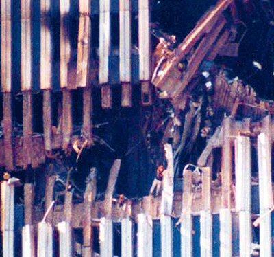
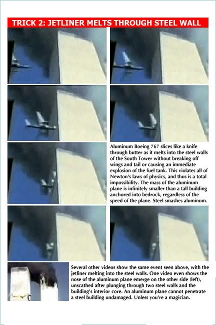
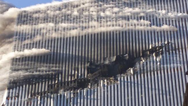
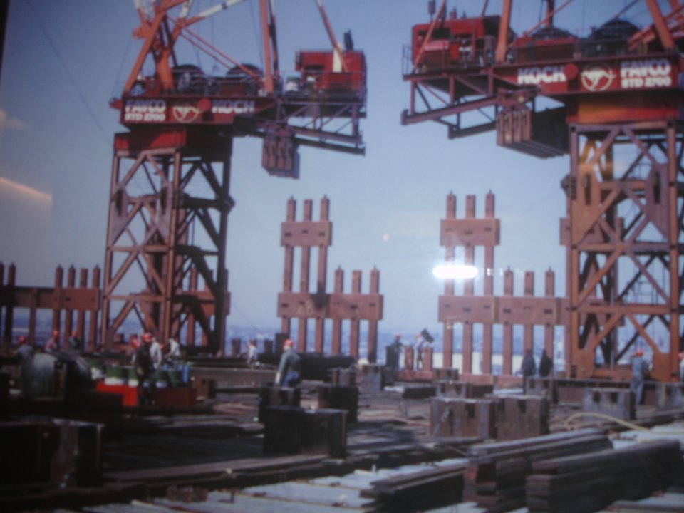
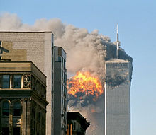
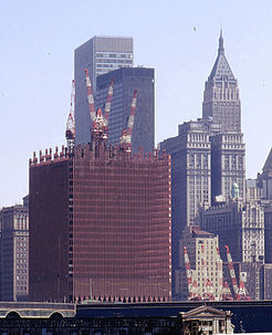
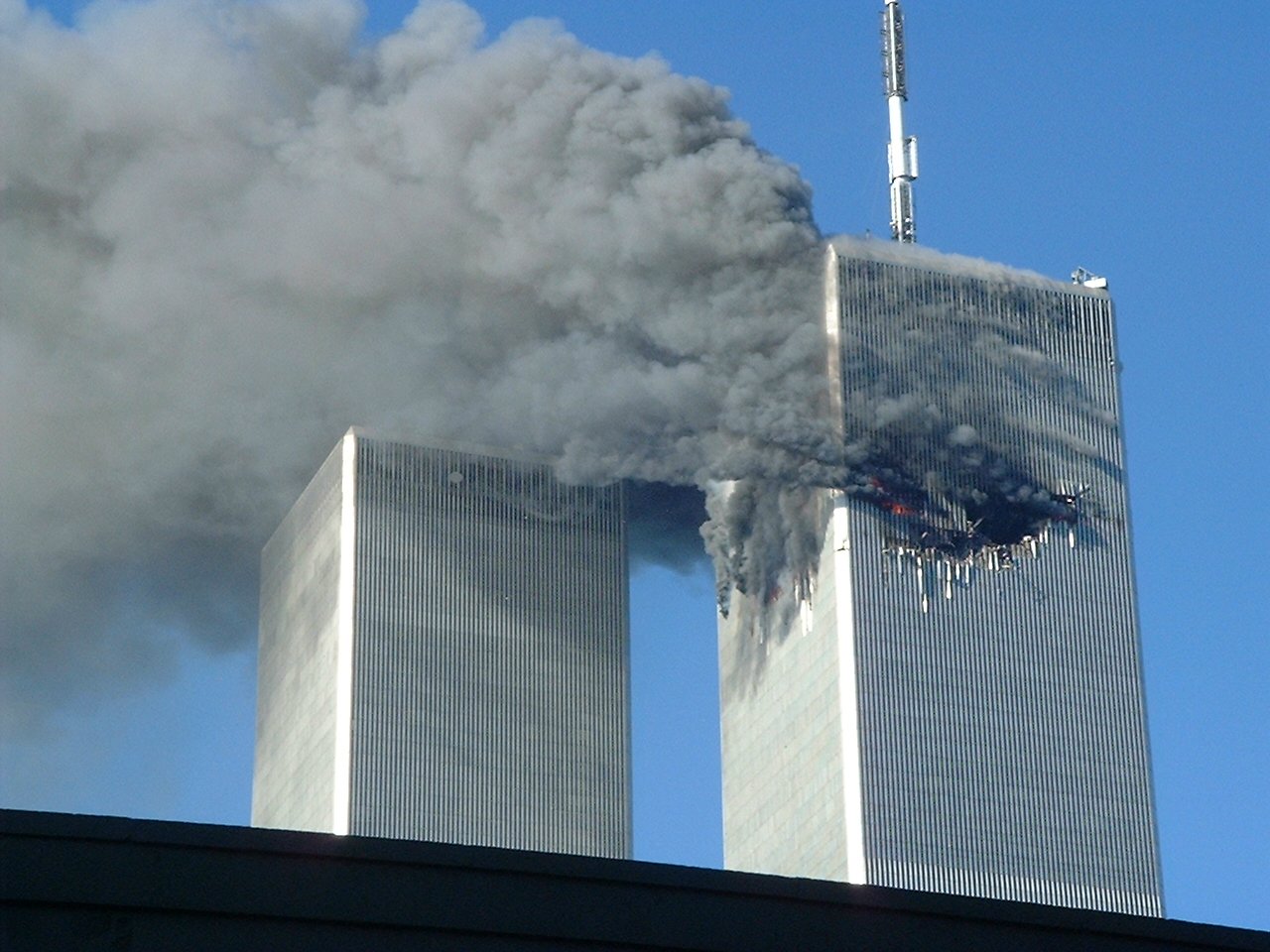
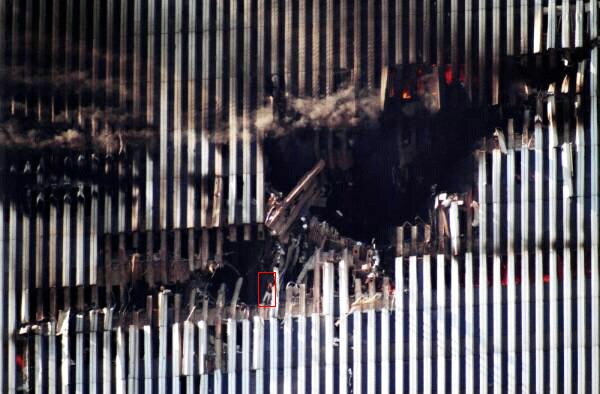
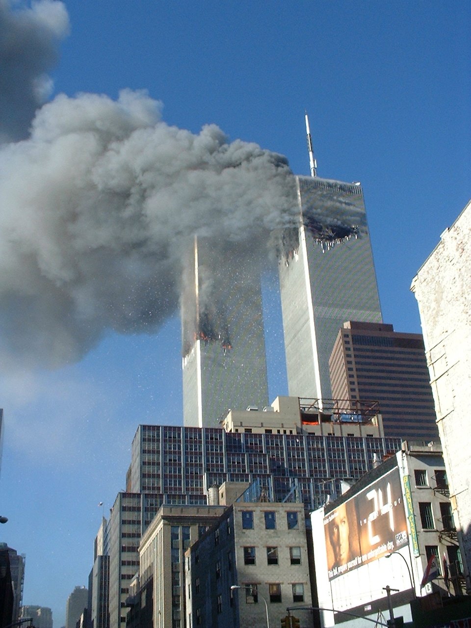